White paperTips for the Installation of MCRT® Torquemeters
White papersAn MCRT® torquemeter must be installed properly as an integral part of a drive line network in order to achieve satisfactory operation. Proper installation will: a) transmit the desired torque load, b) compensate for misalignments in drive line components, and c) not introduce undesirable loading into the torquemeter shaft. Optimum installation must therefore address several key areas: shaft misalignments, coupling types, and torquemeter mountings. This article discusses each of these areas, plus some additional considerations and diagrams of correct and incorrect installations. Shaft Misalignments Drive line component mechanical tolerances will always cause misalignments between the ends of coupled shafts. The misalignment(s) that occur include parallel, angular, and end float. They can and will exist in any combination. Figure 1 illustrates each form of misalignment. Flexible shaft couplings are used to accommodate these misalignments and to transmit the desired torque. The coupling manufacturer will state both the coupling’s torque capacity and misalignment capabilities.
White papersA pioneering biogas company located in central Quebec embarked on an ambitious plan to transform its business model by leveraging advanced technologies, adding new recovery processes, and increasing its on-site treatment capacity. The upgraded and expanded plant features state-of-the-art biomethanization facilities that produce biogas for energy generation along with valuable residues, including biofertilizers. Biomethanization includes several processing stages: material reception, grinding and mixing, hydrolysis, anaerobic digestion and gas management.
White papersAn emission control system was being redesigned by Orbital Engineering, Inc. to incorporate Variable Frequency Drive (VFD) fan systems to improve system efficiency in light of rising process demands. The existing design consisted of two 7,500 hp (5,600 kW) damper-controlled fans, two baghouses, and two spray dryer absorbers. When the system was constructed, one of these flow paths was intended to serve as a standby system, but increased process demands led to both subsystems being used concurrently and fully utilizing maximum installed capacity at times.
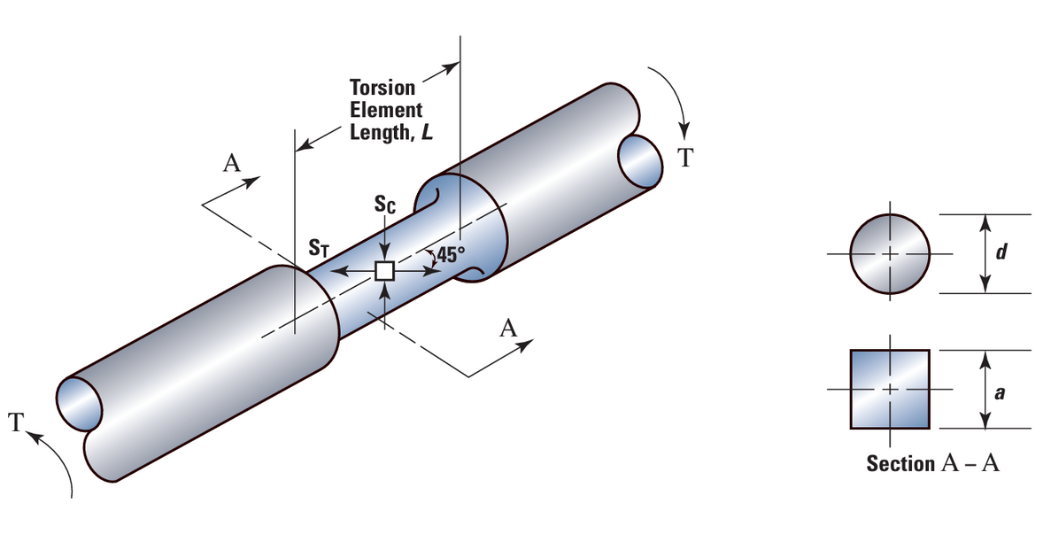
White papersDuring almost 80 years of service, strain gages have proven to be remarkably accurate and reliable mechanical load sensors. They now dominate weighing including static, dynamic, precision and legal for sale applications. They are also used in the vast majority of precision torque sensors. All Himmelstein torque sensors are strain gage based. The simplest torque sensor is depicted in figure 1 below. When torqued, the element is stressed in shear – on a plane through the shaft, perpendicular to the shaft axis. The shear stress creates equal magnitude tensile and compressive stresses at 45 degrees to the shaft axis. Strain gages are installed at 45 degrees to the shaft axis and sense those tensile and compressive stresses.

White papersBackground The recreation complex on the Newham campus of Seneca College, known as ‘the sports center’ was first opened in 1972. As part of an upgrade to the heating system, two new boiler pumps were installed in 2009. Two years later as part of an initiative to extend the installed base of Design Envelope pumps, Armstrong measured the pressure at the gauges on either side of the two pumps. It was discovered that the pumps were actually operating at a much lower performance point than originally specified. Based on the actual requirements of the system, the pumps were oversized, and operating away from their best efficiency point. Armstrong suggested that Seneca replace the pumps with Design Envelope variable speed pumps that would adjust operating speed to match the requirements of the system. To make the retrofit as easy as possible, and avoid any changes to piping, it was suggested that they use the same size pump as originally specified, and take advantage of the variable speed capabilities of the new Design Envelope pump to continually adjust speed and pressure.
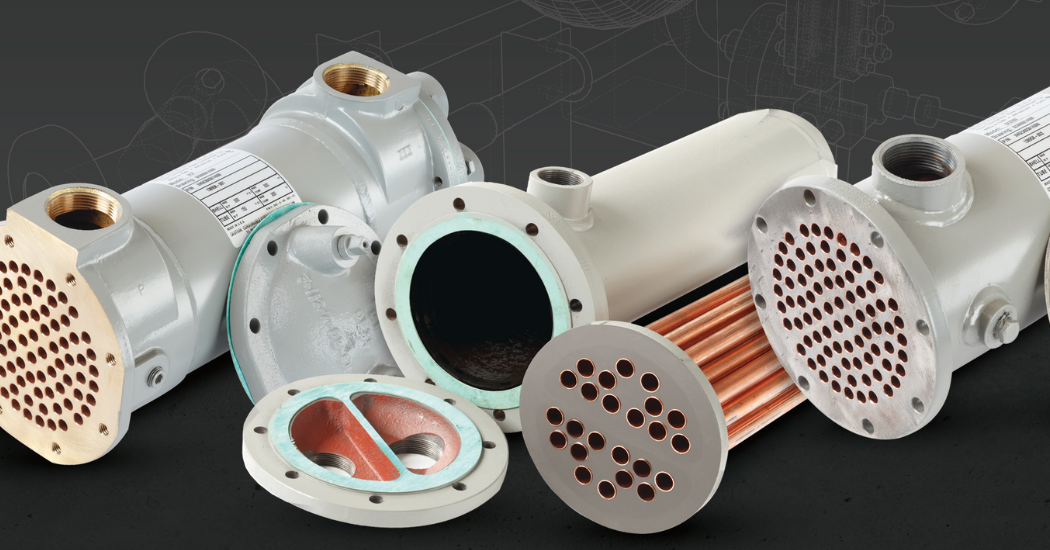
White papersChoosing the right shell and tube heat exchanger for your application Heat exchangers are widely used in various industries including chemical, oil & gas, power generation, food & beverage, HVAC & refrigeration, pulp & paper to name a few, and are expecting strong growth over the coming years driven in part by a rising focus on environmental impact and improving efficiency standards. Although used for varied applications, a heat exchanger’s primary role is to transfer heat from one fluid or gas to another in order to control the temperature of a system and manage waste heat. Growing environmental concerns and regulations are motivating energy-intensive industries to look at ways to improve heat exchanger performance and maximize energy efficiency use. Choosing the right heat exchanger to fit the needs of specific applications and systems is critical in achieving optimal efficiency. Operating conditions, ease of access for inspection and maintenance, and compatibility with process fluids are just some of the variables to be considered when assessing heat exchanger options. Other factors include: Maximum design pressure and temperature Heating or cooling applications Maintenance requirements Material compatibility with process fluids Gasket compatibility with process fluids Cleanliness of the streams Temperature approach A properly selected, installed, and maintained heat exchanger can help enhance the reliability and efficiency of a fluid system by optimizing energy consumption and reducing associated operating costs. In this whitepaper Xylem looks at the specification tips to maximize heat transfer in shell and tube style heat exchangers in order to boost heat exchanger performance and increase efficiency.
White papersChoosing the right plate and frame heat exchanger for your application Heat exchangers are widely used in various industries including chemical, oil & gas, power generation, food & beverage, HVAC & refrigeration, pulp & paper to name a few, and are expecting strong growth over the coming years driven in part by a rising focus on environmental impact and improving efficiency standards. Although used for varied applications, a heat exchanger’s primary role is to transfer heat from one fluid or gas to another in order to control the temperature of a system and manage waste heat. Growing environmental concerns and regulations are motivating energy-intensive industries to look at ways to improve heat exchanger performance and maximize energy efficiency use. Choosing the right heat exchanger to fit the needs of specific applications and systems is critical in achieving optimal efficiency.
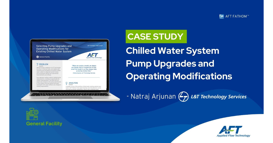
White papersProblem Natraj Arjunan, engineer at L&T Technology Services in Chennai India, was tasked with reviewing and simulating an existing chilled water system to diagnose system issues and recommend design and operational improvements accordingly. Four identical cooling systems needed pump replacements, creating an opportunity for system improvements. The client did not expect any change to the pump specification or the system since the system had been running for 20+ years without any change in cooling requirements.
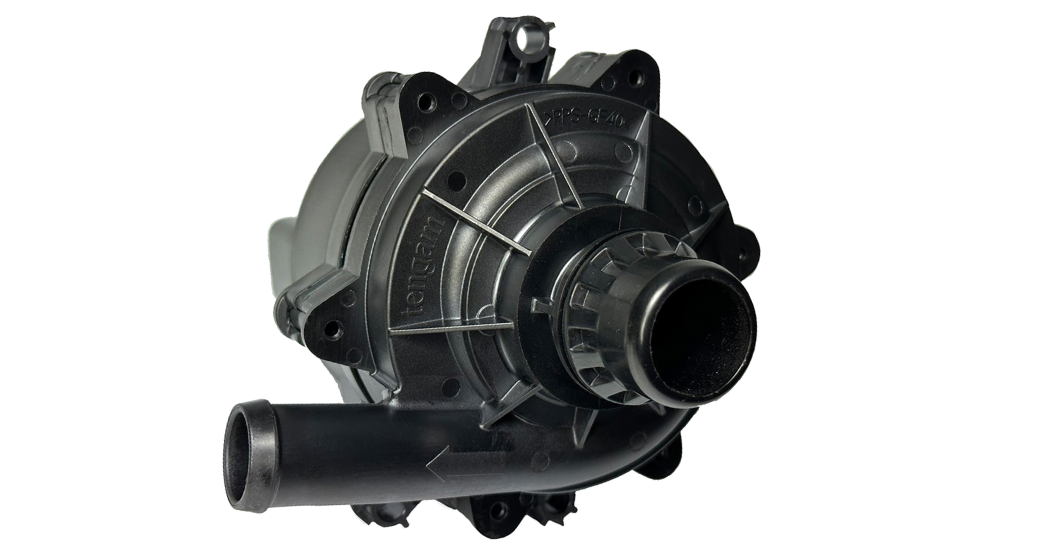
White papersCFturbo presentation at ISimT-24 in Munich/Germany! The paper “All-new Pump Design of an Electric Automotive Coolant Pump” describes a joint development between TENGAM Engineering and CFturbo, Inc. TENGAM Engineering Inc., is an automotive supplier that manufactures injection-molded magnets The company has decided to enter a new market segment: electric automotive coolant pump In cooperation with CFturbo, Inc. an all-new product has been created, a pump with a brushless electric motor CFturbo was responsible for the hydraulic design, CFD simulations, and optimization. Design targets Compact dimensions High efficiency Low noise
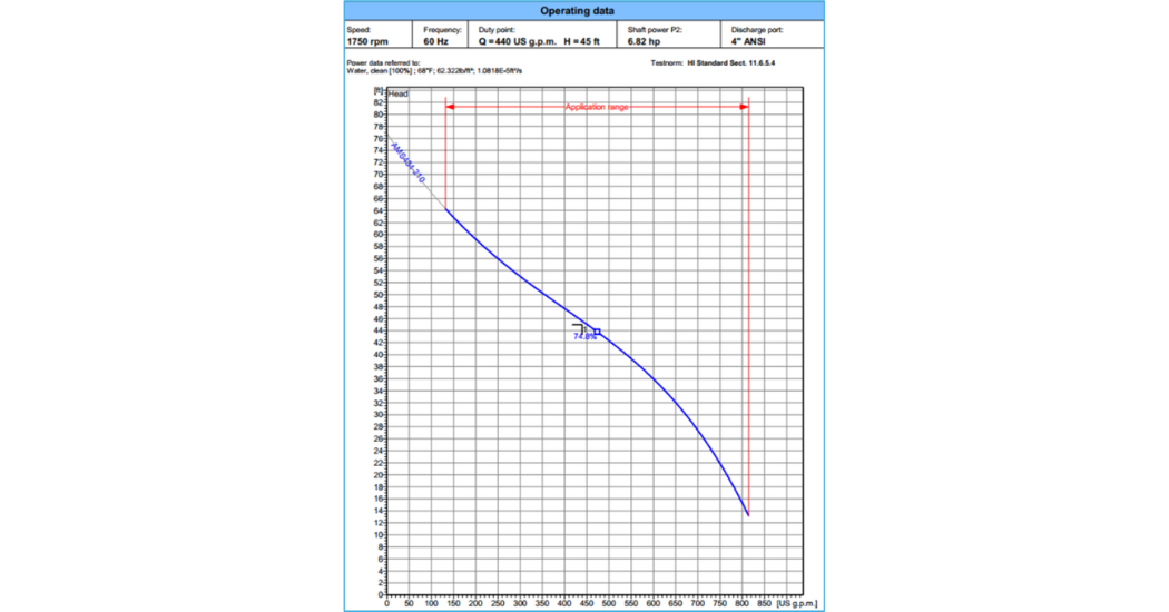
White papersIf you have ever worked with pumps before, be it in an installation, maintenance, or engineering capacity, chances are high you have seen a pump curve. Chances are also high that the first time you saw a pump curve, you had no idea what it meant. That makes sense, because a pump curve is not intuitive at first glance and can be intimidating to someone who is not used to them. However, once you understand some of the basics of curves you will be able to not only understand what they show, but also use them to evaluate a pump’s operation. With this information, you can identify if a pump is meeting its required performance, whether the system is operating as designed, and even prevent pump failures by evaluating if they are operating in a region that may lead to excessive wear and tear. But before we can learn how to use a curve, we have to learn how to read one. In order to talk about pump performance, we need to talk about Flow and Pressure. A pump operating will move a volume of water in a given time (Flow) at a pressure. There are several units of flow that are used, but the most common is gallons per minute (GPM). The most common way to talk about pressure, is what we call “Head.” When talking about the pressure a pump generates, you may hear this referred to as TDH, or Total Dynamic Head. The TDH is the vertical distance (given in Feet in the US) that the pump will push water up. This is very useful when talking about pumping water out of wells, because the depth of the well and the pressure of the pump can both be put in terms of feet. We can convert between psi and feet by multiplying the psi by 2.31. (i.e. 2.31*ft of H20 = psi)
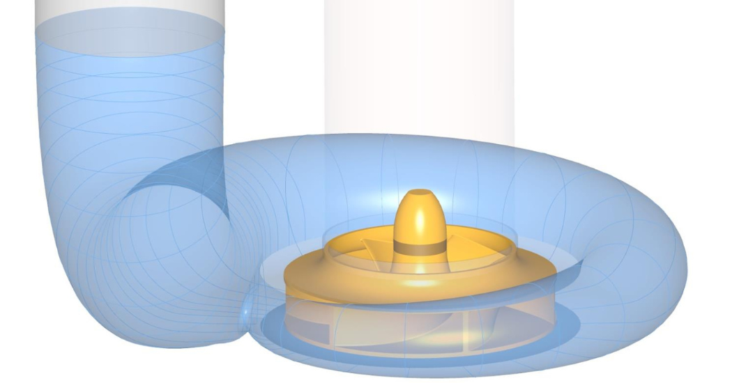
White papersJet fuel pumps play a critical role in the safe and efficient operation of commercial aviation. The performance and reliability of these pumps directly impact aircraft operation, fuel consumption, and overall flight safety. As demands for efficiency, reliability, and environmental sustainability continue to increase in the aviation industry, the optimization of jet fuel pump designs becomes paramount. This report presents a comprehensive study on the optimization of jet fuel pump design utilizing advanced turbomachinery design software, computational fluid dynamics (CFD) simulation tools, and optimization algorithms. CFturbo’s integration with SimericsMP and the Sandia National Laboratories’ DAKOTA optimizer offers a robust and adaptable framework for meeting the performance requirements and enhancing the efficiency of jet fuel pumps. CFturbo provides a powerful platform for the rapid and automated design of turbomachinery components, allowing for the generation of geometric models tailored to specific performance requirements and constraints. SimericsMP, a state-of-the-art CFD software package, enables detailed analysis and 3D simulation of fluid flow phenomena within the jet fuel pump, providing valuable insights into flow behavior, pressure distribution, and performance characteristics. Integrating DAKOTA, a comprehensive and open-source optimization toolkit, further enhances the design process by facilitating the exploration of design parameter space and the identification of optimal solutions. Through the iterative application of design exploration and optimization techniques, this study aims to improve the efficiency and reliability of jet fuel pumps while meeting stringent industry standards and operational performance requirements.
White papersDowntime can be the most expensive element of any manufacturing operation. Here are some important facts and tips you should know to cut down on disruptions in your operation.