
CFturbo is headquartered in Dresden, Germany, with a major office in New York City, New York, and is supported by global network of distributors. Dedicated to turbomachinery design and related engineering services in design of rotating machinery, fluid flow and heat transfer, CFturbo has become a partner with worldwide respect in the turbomachinery community over the last ten years.
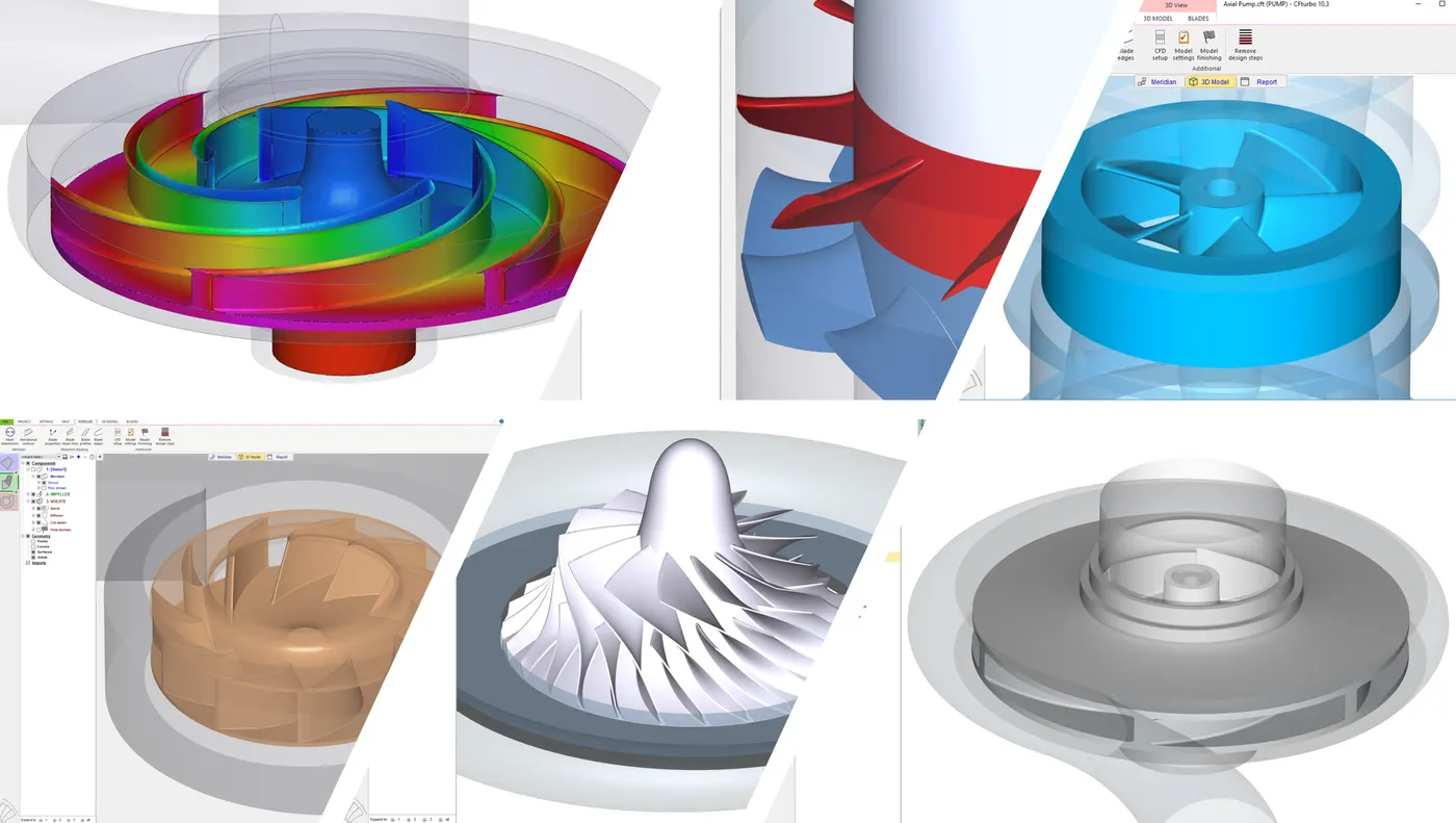
Our conceptual design software CFturbo is the most user-friendly system available on the market. The software can be used to design axial, radial and mixed-flow pumps, fans, blowers, compressors and turbines, as well as for diffusers, stators, return channels and volutes including secondary flow path modeling.
CFturbo offers a number of turbomachinery engineering services including aerodynamic and hydraulic designs, CFD- and FEA-simulation, rotating machinery optimization, mechanical design, prototyping and testing.
From CFturbo
Articles 36


White Papers
- Parametric Modeling for Hydraulic Pump DesignRegister to download
Presented by Ralph Peter Mueller at ASME 2026, this presentation highlights the latest advancements in hydraulic pump design, including Parametric design software, automated high-fidelity 3D flow simulation, user-friendly design exploration, surrogate/meta models, and innovative approaches to developing new conceptual hydraulic pump designs.
- CFturbo BLADERUNNER Design of a Micro Gas Turbine Jet Engine for a DroneRegister to download
Turbojets offer high power density and low mechanical complexity, enabling compact and lightweight propulsion systems well suited for high-speed, space-constrained applications such as UAVs, missiles and other attritional airframes. However, as single-stream engines, turbojets exhibit inherently lower propulsive efficiency than turbofans, placing greater importance on aerodynamic design quality and component-level performance. Within this work, a compressor–turbine pair is developed to meet specified thrust and turbine inlet temperature targets representative of a high-speed drone application, based on industry derived requirements. A Brayton-cycle-based analysis first defines the component-level design requirements, which are then refined through manual iteration. Parametric geometry is generated and adjusted within CFturbo and coupled with external CFD and optimization tools for performance evaluation and design space exploration. The thrust of turbojets is typically between 250 N to about 2,300 N. Manufacturers include JetCat [1] and PBS Aerospace [2]. The present study shows the aerodynamic design of a drone engine with 250 N thrust.
- Gas Turbine Design for a TurbopumpRegister to download
Today, rockets are used to transport satellites and humans into space. These rockets use a cluster of liquid-propellant engines to generate thrust in the lower stage – in some heavy-duty designs with solid-fuel boosters – and in the upper stage often a single liquid-propellant engine of the same type with a thrust nozzle adapted to the vacuum. The enormous thrust generated by a liquid rocket engine is created by the combustion of high mass flows of fuel and oxidizer in the combustion chamber and the subsequent expansion of the combustion gases in the thrust nozzle. In modern liquid rocket engines, the pressure in the combustion chamber reaches up to 30 MPa, with temperatures rising to an extreme 3,000°C. Fuel and oxidizer are stored in liquid state in thin-walled, cylindrical tanks pressurized to approximately 0.5 MPa. The liquid oxygen is cryogenic at -193°C, but even fuels that are liquid at normal ambient temperature are cooled down for maximum density. The two liquids are fed and their pressure increased to a level above the combustion chamber pressure by means of turbopumps.
- Development of a 5,000 lbf Open-Cycle Kerosene-Oxygen TurbopumpRegister to download
Design of a kerosene-oxygen turbopump utilizing a conventional open-cycle system architecture sized to power a 5,000-lbf thrust chamber is described. A conservative design approach tolerant of low performance in return for reduced risk, ease of integration, and lower cost is utilized. The conventional, single-shaft oxygen-kerosene-turbine arrangement is chosen, allowing substantial use of FASTRAC and F1 prior art, and operating speed is maintained well below the first critical speed. Programmatic risk is further reduced through leverage of commercial tools such as CFturbo and Dyrobes for pump and rotordynamic design. Both additive and subtractive manufacturing processes are utilized, and requisite design for manufacture is discussed. Plans and procedures for manufacturing and quality assurance, as well as buildup of test and auxiliary infrastructure are additionally outlined in depth. A team of undergraduates, comprised mostly of first-years, was assembled with the objective to design, build, and test a rocket engine turbopump within the span of approximately one academic year, with a long term goal of a full-stack hotfire within approximately two. Understandably an ambitious target, guidance was provided by a cadre of older team members, with a stronger background in project management built from prior experience with engineering teams. The overall system architecture was authoritatively decided at the beginning of the project: an open-cycle, single-shaft arrangement sized for a blackbox 5000 lbf thrust chamber assembly would be utilized, building upon substantial prior art, given the ubiquity of gas-generator cycles during the Apollo program, as well as continued work on low-cost, high-reliability kerosene-oxygen engines by the FASTRAC and Merlin engine programs. A shaft speed of 50,000 RPM was selected for yielding turbomechanically relevant pump specific speeds and reasonable turbine tip speeds. A conservative, mature architecture would thus be utilized to minimize technical risk, in addition to a design paradigm further emphasizing ease of integration, low cost, and fast development time, even at the expense of performance.
- Autonomous Fontan pump: Computational feasibility studyRegister to download
A double-inlet, double-outlet rotary pump was designed to augment Fontan flow through the total cavopulmonary connection. Pump power is supplied by a systemic arterial shunt and radial turbine, with a closed-loop shunt return to the common atrium. Computational fluid dynamic analysis and lumped parameter modeling of pump impact on the Fontan circulation was performed.
- Hydraulic design of a centrifugal LOX pump, including cavitation modelingRegister to download
The study shows the design and optimization of a LOX centrifugal pump with CFturbo/CFturbo BLADERUNNER 2025.R1 for a fictional rocket engine powered by LOX/RP-1, which delivers around 250 kN thrust at an exit velocity of 3,000 m/s. Current designs such as the medium-weight SpaceX Falcon 9 launcher or the much smaller RFA ONE from Rocket Factory Augsburg, which is still under development, use nine engines in the first rocket stage. Nine of the fictional engines would be enough to launch a payload of 3,400 kg into low earth orbit (LEO).
- CFturbo BLADERUNNER: Centrifugal Pump Design and Model VariationRegister to download
CFturbo, the conceptual Turbomachinery design code, enables engineers to design high-efficiency centrifugal pumps straightforwardly from scratch, or based on a given reference geometry. The all-new CFturbo BLADERUNNER uses Computational Fluid Dynamics (3D-CFD) technology to provide pump performance curves whose accuracy falls within the measurement tolerance of the subsequent test bench runs. In this example, an existing centrifugal pump, designed and set up on a test rig at a German University, has been analyzed. During this specific project, its performance and hydraulic efficiency were improved. Both geometry data and measured values were available. CFturbo offers the unique option of reading existing 3D CAD data and building a parameterized turbomachinery model. Essential flow parameters such as the impeller diameter, blade height, or blade angles can be modified to achieve the previously defined design point with the best possible efficiency.
- Performance Prediction: A Unique Approach for the AftermarketRegister to download
Hydro’s software has allowed CFTurbo to improve the optimize the performance of equipment and its fit to its system to make dramatic efficiency and reliability improvements for their customers. Pumps at first glance appear to be very simple machines. To the layman, there are a number of castings and turned parts bolted together that move liquid around. The truth is far different. Pumps are at the heart of many processes and are vital to our everyday lives. They are one of the most popular machines on the planet and are expected to survive and thrive in the most challenging environments. Pumps are responsible for consuming a lot of power as they are driven to move around the fluids that enhance our lives. This presents a unique opportunity for end users and Hydro’s pump design experts to help the environment by reducing this power consumption and thus reducing both the cost of operation and the emissions generated by the equipment.
- CFturbo BLADERUNNER Centrifugal End-Suction Pump CasestudyRegister to download
The CFturbo BLADERUNNER 2024 is a unique and innovative tool that will outperform the known capabilities of an automated simulation process for Turbomachinery performance maps. The new CFturbo BLADERUNNER controls the interaction of our conceptual Turbomachinery 3D-CAD system CFturbo with the 3D-CFD software CFturbo SMP (Simerics MP). This combination offers a user-friendly, robust, and affordable solution to predict Turbomachinery performance accurately, making it a tool of great interest to professionals and newcomers in the field.
- All-New Hydraulic Design of an Electrical Automotive Coolant PumpRegister to download
CFturbo presentation at ISimT-24 in Munich/Germany! The paper “All-new Pump Design of an Electric Automotive Coolant Pump” describes a joint development between TENGAM Engineering and CFturbo, Inc. TENGAM Engineering Inc., is an automotive supplier that manufactures injection-molded magnets The company has decided to enter a new market segment: electric automotive coolant pump In cooperation with CFturbo, Inc. an all-new product has been created, a pump with a brushless electric motor CFturbo was responsible for the hydraulic design, CFD simulations, and optimization. Design targets Compact dimensions High efficiency Low noise
- Design Optimization of Jet Fuel Pump for AviationRegister to download
Jet fuel pumps play a critical role in the safe and efficient operation of commercial aviation. The performance and reliability of these pumps directly impact aircraft operation, fuel consumption, and overall flight safety. As demands for efficiency, reliability, and environmental sustainability continue to increase in the aviation industry, the optimization of jet fuel pump designs becomes paramount. This report presents a comprehensive study on the optimization of jet fuel pump design utilizing advanced turbomachinery design software, computational fluid dynamics (CFD) simulation tools, and optimization algorithms. CFturbo’s integration with SimericsMP and the Sandia National Laboratories’ DAKOTA optimizer offers a robust and adaptable framework for meeting the performance requirements and enhancing the efficiency of jet fuel pumps. CFturbo provides a powerful platform for the rapid and automated design of turbomachinery components, allowing for the generation of geometric models tailored to specific performance requirements and constraints. SimericsMP, a state-of-the-art CFD software package, enables detailed analysis and 3D simulation of fluid flow phenomena within the jet fuel pump, providing valuable insights into flow behavior, pressure distribution, and performance characteristics. Integrating DAKOTA, a comprehensive and open-source optimization toolkit, further enhances the design process by facilitating the exploration of design parameter space and the identification of optimal solutions. Through the iterative application of design exploration and optimization techniques, this study aims to improve the efficiency and reliability of jet fuel pumps while meeting stringent industry standards and operational performance requirements.
- Contra-Rotating Axial Fan Design Concept for Leaf BlowersRegister to download
It seems leaf blowers are everywhere in our neighborhoods, very often disturbingly noisy. There is a need for excellent aerodynamic and aeroacoustics design for such devices. Three leaf blower configurations were designed using CFturbo: a single-stage design, a dual-stage design, and a contra-rotating design. The goal of the design study is to minimize the rotational speed required to meet the performance targets and minimize the swirl downstream of the nozzle. The design point volume flow rate was set to 500 cfm at 25,000 rpm with a total pressure difference of 3,000 Pascals. Although the relationship between sound output and rotational speed is not directly proportional, higher rotational speeds often result in remarkably increased noise levels due to higher airflow velocity, higher blade tip speeds, higher frequency noise components, and increased flow instabilities. A robust acoustic design optimization would require extensive simulation and testing. By reducing the downstream swirl, the user has improved directional control over the airflow leaving the device.
- Design Optimization of a Centrifugal Compressor [Case Study]Register to download
Conceptual design of a centrifugal compressor R134a Software: CFturbo, integrated into Ansys Workbench One initial design + one manual design variation, “Design2” Mathematical optimization using CFturbo/Ansys Workbench/Design Explorer 8 geometry parameters, 141 different designs in total All design points meet the performance requirements at selected rpm Substantial stage efficiency improvement at design speed Initial design: η=56% Manual “Design2”: η= 59% Optimized “Design107”: η= 73% Total project time: 10 days Next steps Adjustments and fine-tuning, for example blade loading variation and volute parameters 360° impeller model and transient simulations for final check of steady-state results
- Design And Investigation Of A Multistage Axial Contra-Rotating FanRegister to download
The development of a multistage axial fan using contra-rotating wheels at each stage is described here. The outer diameter of the fan is 120 mm and the rotational speed for the first and the second impeller are 133.3 s-1 and 83.3 s-1, respectively. The design of the complete fan is based upon the design approach for contra-rotating axial fans of CFturbo [12]. The first impeller was designed for a performance of 2/3 of the overall power. Hence, it was not necessary to fulfill the balancing of momentum although that is an available design option in CFturbo [12] amongst others. The contra-rotating axial fan is examined with different methods. Performance measurements and measurements on the velocity profile with optical methods (PIV) are provided to understand the working principle of every stage. The high efficiency and the axial outlet flow without tangential velocity components (swirl) are demonstrated with these measurements. Figure 4: 3D geometry of the fan
- Optimization of an Axial Pump using CFturbo, Simerics and optiSLangRegister to download
The workflow presented here describes the fast and cost-effective optimization of an axial pump with modern software tools. Motivation Turbomachinery design is still very complex and time-consuming if it is executed manually. In order to save time and thus reduce costs, automatic optimization is a suitable approach. The following describes a robust and easy to use optimization workflow using 3 state-of-the-art software tools: CFturbo, SimericsMP and optiSLang.
- Detecting Potentially Unstable Cavitation Modes with Computational Fluid Dynamics (CFD) AnalysisRegister to download
INTRODUCTION Cavitation is a thermodynamically non-reversible process defined as the formation and subsequent collapse of vapor bubbles caused by the drop in pressure in the fluid domain, as illustrated in Figure 1. The collapse of these bubbles can produce a shock wave strong enough to damage machine parts, and as such, cavitation is usually an undesirable phenomenon. It can also generate significant vibration and noise, cause rotordynamic instabilities and blade erosion, and negatively affect general machinery performance.
- A Complex Approach Using Splitter Blade Impellers To Improve Centrifugal Pump PerformanceRegister to download
This work presents the results of complex research of changes in the hydraulic, stress-strain state and dynamic characteristics of the double-entry single stage pump (specific speed nq=55) in the case of introduction of splitter blades in the basic design are presented in this paper. Since the splitter blades modify flow within the blade-to-blade channel, the energy loss will depend on their shape. Determination of the maximum possible increasing of impeller head while maintaining or increasing the efficiency is connected with multiparametric optimization of the splitter blades geometry. Geometrical dimensions determining the shape and position of the splitter blades were used as variable parameters. Head and efficiency are the objective functions. Determination of hydrodynamic flow parameters was carried out by using the CFD meth- ods. In this paper some thoughts regarding the influence of the shape and location of the splitter blade on the distribution of flow parameters are discussed. Comparative analysis of strength and vibration characteristics of the pump with the original impeller and splitter blade impellers carried out on the basis of FEM-analysis. The results of the this study highlighted aspects allow us to conclude that to ensure reliable operation of the pump approach to splitter blade impeller design should be more consistent and comprehensive.
- Non-Propeller Propulsion System for a Human Powered SubmarineRegister to download
Background The International Submarine Races (ISR) is a competition in which teams race “wet” submarines. A “wet” submarine is an internally flooded, fully enclosed, vehicle in which the pilot(s) must breathe from a SCUBA apparatus [1]. The racecourse is a 100 yard straight sprint. The submarines compete in four categories: 1 and 2 person propeller, and 1 and 2 person non-propeller. A propeller system is defined as a water-coupled device with radiating blades that create thrust when spinning. A non-propeller system is defined as any other water-coupled device that creates a thrust when operated. A bottom crawling vehicle is not a water-coupled device [1]. The University of Michigan Human Powered Submarine Team (HPS) traditionally builds single person propeller driven submarines [1]. The Problem HPS wants us to develop and create a non-propeller propulsion module that can take the place of the current propeller module in order to compete at the International Submarine Races in the -non-propeller category. The new, non-propeller propulsion system must be able to be easily switched with the current propulsion system without affecting the rest of the submarine. Benchmarks Submarines predominantly use propellers, even the standard screw propeller can produce high efficiency on the order of 80 percent. [2] However, jet propulsion is also used where water is drawn in and thrust out near the stern. This leads to no moving parts outside the main hull, so jet propulsion tends to be used in shallow water applications. Since an impeller is used to pump the water, the overall efficiency is less than that of a propeller system because of friction loss from the inner wall ducts. [3] Propellers and jet propulsion are the two main systems in use by submarines today. Magnetohydrodynamic (MHD) systems are being researched but are not in commercial use. One of the main problems is the relative efficiency compared to other forms of propulsion. The efficiency of a MHD system is proportional to the magnetic flux intensity, so very powerful magnets are needed. [4] To find other comparable models to what we are trying to achieve, other submarines in the human powered submarine competition and other underwater systems need to also be studied. Figure 7a (Left) : CAD model of Impeller Module; Figure 7b (Right): Cutaway view of Impeller Module Background The International Submarine Races (ISR) is a competition in which teams race “wet” submarines. A “wet” submarine is an internally flooded, fully enclosed, vehicle in which the pilot(s) must breathe from a SCUBA apparatus [1]. The racecourse is a 100 yard straight sprint. The submarines compete in four categories: 1 and 2 person propeller, and 1 and 2 person non-propeller. A propeller system is defined as a water-coupled device with radiating blades that create thrust when spinning. A non-propeller system is defined as any other water-coupled device that creates a thrust when operated. A bottom crawling vehicle is not a water-coupled device [1]. The University of Michigan Human Powered Submarine Team (HPS) traditionally builds single person propeller driven submarines [1]. The Problem HPS wants us to develop and create a non-propeller propulsion module that can take the place of the current propeller module in order to compete at the International Submarine Races in the -non-propeller category. The new, non-propeller propulsion system must be able to be easily switched with the current propulsion system without affecting the rest of the submarine. Benchmarks Submarines predominantly use propellers, even the standard screw propeller can produce high efficiency on the order of 80 percent. [2] However, jet propulsion is also used where water is drawn in and thrust out near the stern. This leads to no moving parts outside the main hull, so jet propulsion tends to be used in shallow water applications. Since an impeller is used to pump the water, the overall efficiency is less than that of a propeller system because of friction loss from the inner wall ducts. [3] Propellers and jet propulsion are the two main systems in use by submarines today. Magnetohydrodynamic (MHD) systems are being researched but are not in commercial use. One of the main problems is the relative efficiency compared to other forms of propulsion. The efficiency of a MHD system is proportional to the magnetic flux intensity, so very powerful magnets are needed. [4] To find other comparable models to what we are trying to achieve, other submarines in the human powered submarine competition and other underwater systems need to also be studied.
- Design and Analysis of a High Speed, High Pressure Peroxide/RP-1 TurbopumpRegister to download
In the past, hydrogen peroxide bipropellant rocket engines were reserved for limited performance applications such as propulsion for rocket-assisted take-off (RATO) or sounding rockets due to the use of pressure-fed propellants or low-performance turbopump cycles. However, research performed at Purdue University has indicated silver screen catalyst beds used to decompose hydrogen peroxide can operate at much higher bed loadings and pressures than previously believed. Thus, leveraging modern technology to substantially increase the performance of such engines, a single-shaft, radial turbine, centrifugal impeller turbopump has been designed to deliver high-pressure hydrogen peroxide and RP-1 to a compact and lightweight 5,000 lbf rocket engine. The turbopump is extraordinarily small and fast, fitting within a 150 in3 envelope, spinning at 90,000 RPM, and delivering propellants at pressures close to 6,000 psig. Benchmarked against the Bristol-Siddeley 605 RATO engine, the developed engine delivers a 50% greater thrust-to-weight ratio, confirming that modern technology and design tools can be used to produce rocket engines that greatly outperform heritage systems of similar configuration.
Ask CFturbo
Questions about a product, a quote or a spec? Send your request and we pass it to the right contact at CFturbo.
Loading the request form