
Learn
White Papers
Technical papers and guides from the companies that publish here, free to download.
Technical papers and guides from the companies that publish here, free to download.


554 white papers
This guide from S. Himmelstein & Company details their torque sensor solutions, designed to meet the demands of any industry. Learn about: Ultra-Precise Spline Drive per AND C-Face Hollow Flanged Compact Digital Bearingless Digital
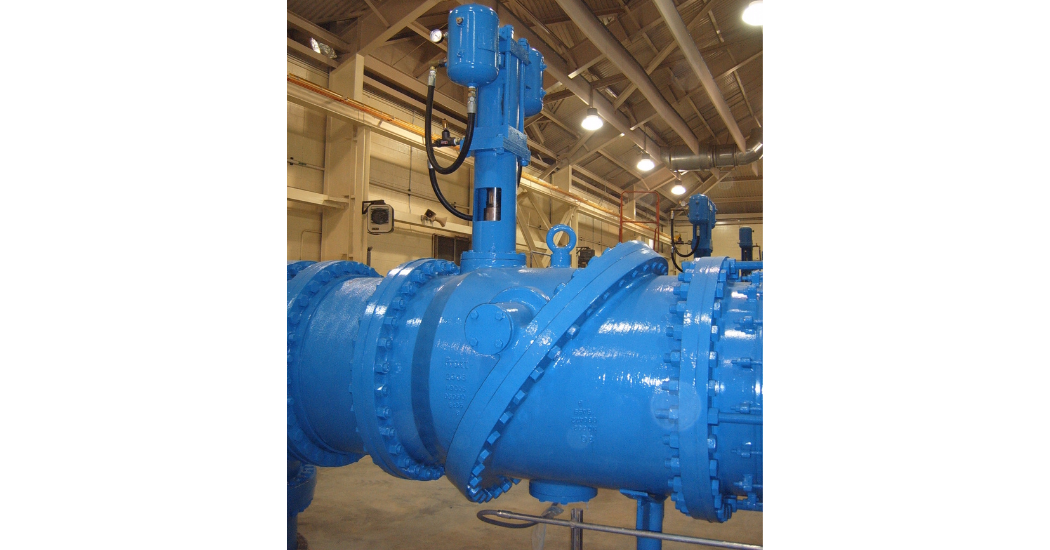
Water hammer (or hydraulic shock) is the momentary increase in pressure inside a pipe caused by a sudden change of direction or velocity of the liquid in the pipe. Water hammer can be particularly dangerous because the increase in pressure can be severe enough to rupture a pipe or cause damage to adjoining flow control equipment. Physical Origins of Water Hammer Water, an incompressible media, flowing within a pipe will possess three types of physical energy: Pressure, kinetic and potential. Pressure energy relates to the static or standing energy of the media, kinetic energy relates to the media velocity and potential energy relates to the relative elevation of the media (potential change in pressure) in the pipeline. All forces of pipe friction aside, the combination of pressure, kinetic and potential energy will remain constant at all points throughout the length of the pipeline. Due to the physical Law of Conservation, where energy cannot be created nor destroyed, changing the magnitude of the kinetic energy, by changing the fluid velocity, will have a direct effect on the magnitude of pressure or potential energy elsewhere in the pipe. If the velocity of the liquid decreases (decrease in kinetic energy), the fluid pressure could increase (increase in pressure energy). Water hammer most commonly occurs when water is flowing through a pipeline and a pump is stopped or a valve is quickly closed. The sudden halt in fluid flow in the pipeline will produce a pressure spike in the form of a shock wave, which will travel back and forth down the piping system, reflecting back from the end of the pipeline. The maximum velocity of this shock wave will be equal to or less than the speed of sound for that specific fluid. For example, water at 70 degrees Fahrenheit has a sound wave velocity of over 4800 ft/sec (1463 m/sec). However, the dampening effect by which the material the pipeline is made from, affects and dictates the terminal velocity of the pressure wave. The shock wave will continue to oscillate back and forth down the pipeline, between the closed valve on one end and the end of the line, until the energy is absorbed, and the pressure soon equalizes in the pipeline. If a pump stops or a valve rapidly closes while the fluid is in motion, two things can happen: 1) The line velocity moving toward the valve disc will rapidly decelerate and impose a sudden high (positive) pressure force and thus create a propagating pressure wave as defined above. 2) The opposite side of the valve, where line velocity was flowing away from the valve, will attempt to sustain the line velocity by working off of its kinetic energy. As the flow media attempts to maintain the line velocity, the pipeline will experience a sudden (negative) pressure force or vacuum, where the column of fluid will try to separate as the line velocity continues to move away from the valve. This is called column separation. Column separation is a vacuum pocket where the vacuum pressure is continuous through the downstream end of the pipeline. Column separation creates a negative pressure, which can be sufficient enough to cause the pipe to collapse, especially in a circumstance when the pipeline is located on a slope where the water is flowing downhill. Valve placement is important to maintaining pipe integrity. Therefore, a valve should never be placed at the top of the hill without a downstream vacuum breaker valve in close proximity. Otherwise a valve that is closed at the top of the hill possesses a greater tendency to allow negative pressure to occur which can result in the collapse of the pipe. The use of a slow closing isolation valve on pump control will eliminate water hammer compared to using check valves. The check valve does prevent flow reversal, but at a cost. The rapid close action of a check valve will never be able to stop flow reversal before the pumping action ceases. Therefore, the slight flow reversal that suddenly stops against the back side of a check valve disc could produce a significant level of water hammer. The use of external air or hydraulic cushions to slow the closing motion of the check valve offers only some benefit. The single most assured way to eliminate any water hammer on a pump control application is to utilize a control valve that will proactively close on command rather than reactively close due to sensing flow reversal. The Sequence of Operation for a pumping application should commence as follows: Pump Start-up 1) Pump control valve is fully closed and pump is commanded to start. 2) Pump starts and pressure developed between the pump and the closed valve will be equal to or slightly greater than the downstream static pressure of the pipeline. 3) A pressure sensor senses the pipeline pressure and pump pressure have equalized and thus sends a command to SCADA to open the pump control valve. 4) The pump control valve will begin to open, but at a rate that has been determined (through a surge analysis) to not produce a pressure spike in the pipeline due to excessive flow surge. 5) The valve opens fully without producing a pressure spike and the pump continues its pumping obligation. Pump Shutdown 1) After the pumping obligation has been satisfied SCADA will commence the pump shutdown sequence by first closing the pump control valve. 2) Due to the results of the surge analysis the minimum time required to close the pump control valve – without producing a pressure spike or column separation – has been defined and therefore the pump control valve will commence. Valve closure is performed however while the pump continues to run. If the pump were to stop running before the valve is fully closed flow reversal would occur and impart unnecessary harm, in the form of a pressure spike, to the pipeline and possibly backspin the pump, thus causing further unnecessary mechanical harm. NOTE: the rate at which the valve can open or close must be independent of each other and field adjustable. To this end, electric operators use fixed gearing to develop the mechanical advantage required to operate a valve. Thus, it will only have one (fixed) rate of operation for both open and close. This approach is not a good option to control water hammer. 3) As the pump control valve approaches the full closed point a switch located on the pump control valve position indicator will trip and this will be the signal for SCADA to command the pump to stop. 4) The pump control valve closes and the pump stops flowing water. The end result is no pressure surges were produced and this approach can be used on all types of pump control applications. Download to Learn How to Minimize Water Hammer and Formulas for Doing So!

Benefits that improve your torque measurements Best real-world accuracy Highest Overload Highest Overrange

Introduction As a plant/maintenance manager or reliability engineer for a water or wastewater facility, you want to know about the best technologies to help your team spend less time on seal and pump installation and maintenance, reduce long-term equipment costs, and save energy and water. When pump disassembly is involved, especially for larger equipment, maintenance expenses and downtime can lead to enormous costs. For example, a municipal client we recently worked with calculated that it costs them $3k per pump on disassembly labor and downtime. An estimated 70 – 80% of unscheduled pump shutdowns are seal/packing related. That makes it essential that you plan ahead with the best available technologies to avoid these issues and related costs. This book will show you how. What is this E-Book About? Learn about advanced sealing technologies and state-of-the-art configurations to help maximize the life of your pumps and other rotating equipment, plus: Traditional sealing methods for pumps and mixers at water and wastewater facilities, including the advantages and disadvantages of each. Split seal technology and how it can drastically lower maintenance costs and downtime, as well as improve overall equipment reliability. How active throat bushing technology can greatly enhance the seal environment with minimal or no flush water requirements. Equipment monitoring of critical operating parameters that can impact seal performance. Real world success stories using these sealing technologies and configurations. Specific Chesterton® product recommendations by water and/or wastewater processing application areas.

“Himmelstein’s Thrustmeter has proven to be accurate and repeatable, which are two of the main things that define quality in an instrument. It’s been a reliable instrument to help us differentiate and diagnose areas of failure for our customers” – Thomas Papadakos, Test Lab Manager, Hydro, Inc. “Our focus primarily is to make sure that we develop products and offer features in our products that give them technical advantage over the competition. So, they either have better accuracy, better performance, better characteristics than what our competitors offer.” – Steven E. Tveter, Vice President, S. Himmelstein and Company Download this whitepaper to learn more about Thrustmeters and read a case study about Hydro, Inc.

Take Action Today To Make Your Pumps More Efficient Pump motor power levels and energy consumption provide valuable input about the status of and changes to the pumping subsystem over time. Knowing the energy footprint of each pump/motor combination enables informed decisions about efficiency and utilization. When viewed over time, this data can provide additional data on system degradation and maintenance needs. A properly maintained and right-sized pumping subsystem means efficient energy use, and a reduced environmental impact.

Despite the complex structure of the Mater Dei hospital in Betim, Armstrong was able to deliver a reliable, energy efficient solution with the ipc 9511 installation. The project was recognized with a 2022 ashrae Technology Award in the category of New Healthcare facilities. The Armstrong Integrated Air-Cooled Chiller Plant Control System (ipc 9511) boosts performance of new and existing chiller plant installations to deliver optimum efficiency and occupant comfort. Along with the Design Envelope 4300 pumps, an ipc 9511 reduces installation costs, operating costs and performance risk.
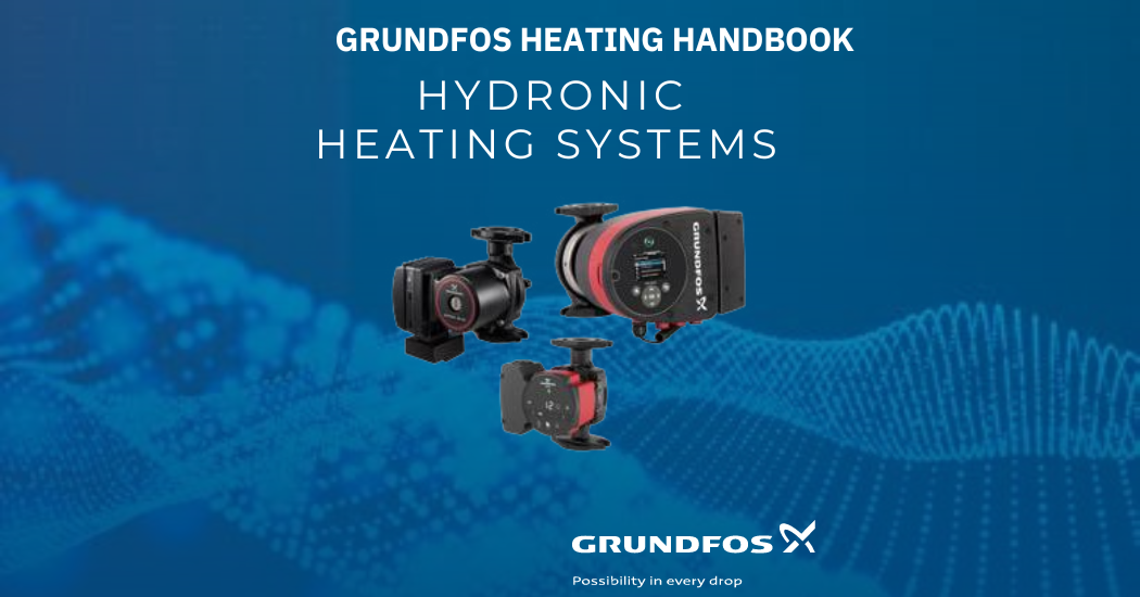
Grundfos’ NEW Hydronic Heating Handbook is now available. This comprehensive resource offers valuable insights into hydronic piping strategies, pump sizing, selection, troubleshooting tips, and more. Whether on the job or on the go, users can access the handbook easily from any smart device.

Laminar structure: The molecular structure of carbon graphite consists of layers of carbon atoms arranged in flat and parallel structures, providing high mechanical strength and dimensional stability, which is crucial in applications where resistance to deformation under high loads is required. Learn more about carbon graphite and find out how it can help in your industry!
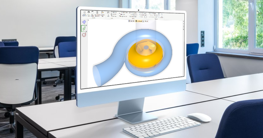
The CFturbo BLADERUNNER 2024 is a unique and innovative tool that will outperform the known capabilities of an automated simulation process for Turbomachinery performance maps. The new CFturbo BLADERUNNER controls the interaction of our conceptual Turbomachinery 3D-CAD system CFturbo with the 3D-CFD software CFturbo SMP (Simerics MP). This combination offers a user-friendly, robust, and affordable solution to predict Turbomachinery performance accurately, making it a tool of great interest to professionals and newcomers in the field.
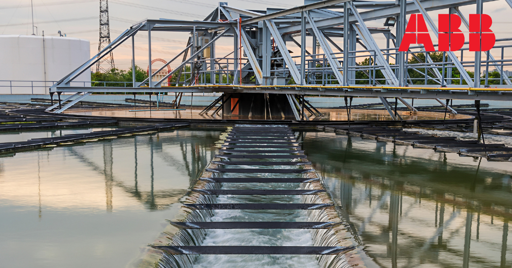
Download ABB’s new playbook to help you identify and defeat the enemies that interrupt your water/wastewater operation and learn how you can… • Reduce operational headaches due to poor utility power • Boost generator stability and prevent nuisance tripping • Avoid breaks, spills, and bursts that risk licenses and permits • Extend asset life in extreme environments • And more… Gain valuable insights into how ABB’s designed for your industry, Variable Frequency Drives (VFDs) can improve your pump and blower processes and protect aging assets.
Sodium hypochlorite (NaOCl) is widely used by municipal water treatment plants Sodium hypochlorite (NaOCl) is an effective water disinfectant to treat the raw, filtered water before distribution. But sodium hypochlorite can be an unstable solution when exposed to heat and light, that needs to be stored in tightly closed containers and kept in a cool place away from direct sunlight. Otherwise elevated temperatures will cause it to decompose or “off gas” creating gaseous oxygen (O2) that builds up gas bubbles in the chemical metering feed system. A common metering feed pump technology used to meter the sodium hypochlorite is Electrically Operated Double Diaphragm (EODD) pumps that can precisely inject the volume of chemical the system requires. However, EODD pumps are very prone to vapor locking when gas bubbles build up in the feed system, causing them to bind and stop pumping the sodium hypochlorite. To fix these situations, the EODD pumps must be manually vented to release the built up gases, so the EODD pumps can begin pumping again. This manual venting process can occur as many as several times a month during warmer periods of the year, requiring plant personnel to be on hand each time or even make a special visit to the treatment station if after hours, to vent the EODD pump and get it back online. The required labor cost to manually vent the EODD pumps can be significant over the course of a year, adding up to several thousand dollars per pump. There’s also additional pump maintenance parts and maintenance labor costs as well, adding well over another thousand dollars per pump, per year of expense. All totaled, the EODD pump’s annual operation and maintenance cost can be in excess of $3,600 per pump, per year. The following calculations provide typical EODD expenses in this service.