

Mueller is a leading manufacturer and marketer of products and services used in the transmission, distribution and measurement of water. We help municipalities increase operational efficiencies, improve customer service and prioritize capital spending demonstrating why Mueller is Where Intelligence Meets Infrastructure®.
From life-saving fire protection to data intelligence, we develop products and solutions that help cities and water utilities deliver clean, safe drinking water. Our broad product and service portfolio includes engineered valves, fire hydrants, pipe connection and repair products, metering products, leak detection, pipe condition assessment and pressure management products.
Mueller can fulfill your water system needs from end to end – at the source, at the plant, below the ground, on the street and in the cloud.
800-423-1323
www.muellerwaterproducts.com
From Mueller Water Products
Articles 75


Products 16
Mueller Water Products
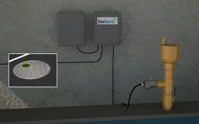
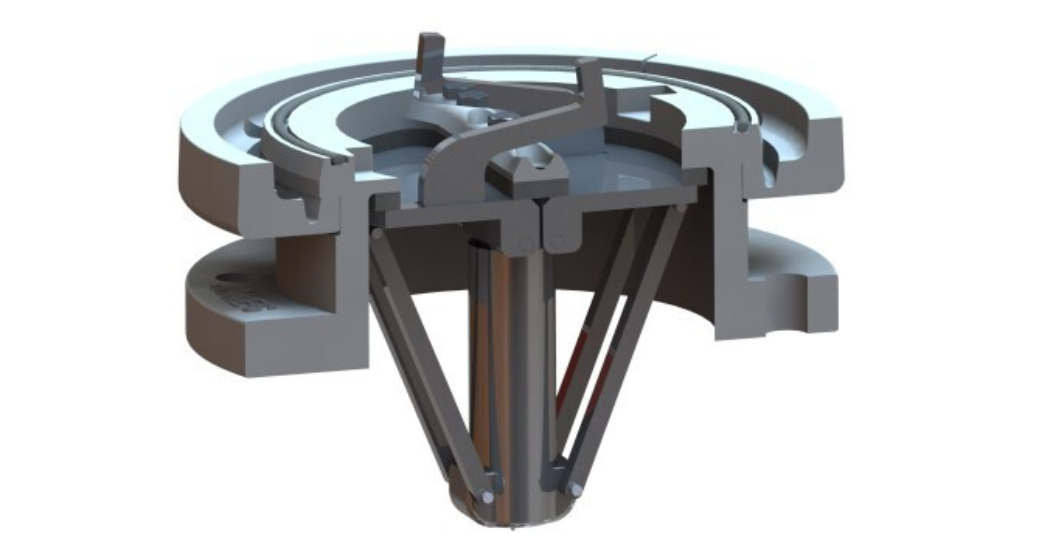
EchoShore-TX Large Diameter Leak Monitoring System
Mueller Water Products
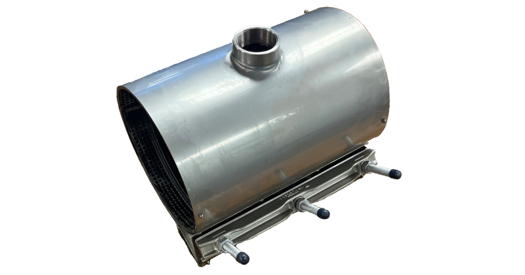
HYMAX® Clamp with added outlet option for service connections or temporary bypass
Mueller Water Products
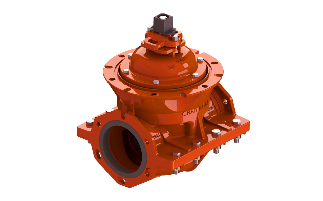
H-2361 Mueller® Insertion Valve
Mueller Water Products
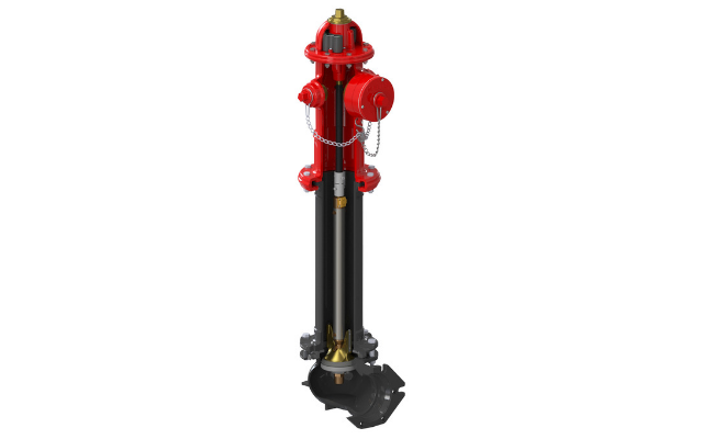
Super Centurion® Dry Barrel Fire Hydrant
Mueller Water Products
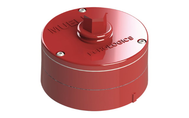
EchoShore®-DX Node latest in Fixed Leak Detection & now on the 4G LTE network
White Papers
- What is Water Hammer and Why It Is Important to Prevent?Register to download
Water hammer (or hydraulic shock) is the momentary increase in pressure inside a pipe caused by a sudden change of direction or velocity of the liquid in the pipe. Water hammer can be particularly dangerous because the increase in pressure can be severe enough to rupture a pipe or cause damage to adjoining flow control equipment. Physical Origins of Water Hammer Water, an incompressible media, flowing within a pipe will possess three types of physical energy: Pressure, kinetic and potential. Pressure energy relates to the static or standing energy of the media, kinetic energy relates to the media velocity and potential energy relates to the relative elevation of the media (potential change in pressure) in the pipeline. All forces of pipe friction aside, the combination of pressure, kinetic and potential energy will remain constant at all points throughout the length of the pipeline. Due to the physical Law of Conservation, where energy cannot be created nor destroyed, changing the magnitude of the kinetic energy, by changing the fluid velocity, will have a direct effect on the magnitude of pressure or potential energy elsewhere in the pipe. If the velocity of the liquid decreases (decrease in kinetic energy), the fluid pressure could increase (increase in pressure energy). Water hammer most commonly occurs when water is flowing through a pipeline and a pump is stopped or a valve is quickly closed. The sudden halt in fluid flow in the pipeline will produce a pressure spike in the form of a shock wave, which will travel back and forth down the piping system, reflecting back from the end of the pipeline. The maximum velocity of this shock wave will be equal to or less than the speed of sound for that specific fluid. For example, water at 70 degrees Fahrenheit has a sound wave velocity of over 4800 ft/sec (1463 m/sec). However, the dampening effect by which the material the pipeline is made from, affects and dictates the terminal velocity of the pressure wave. The shock wave will continue to oscillate back and forth down the pipeline, between the closed valve on one end and the end of the line, until the energy is absorbed, and the pressure soon equalizes in the pipeline. If a pump stops or a valve rapidly closes while the fluid is in motion, two things can happen: 1) The line velocity moving toward the valve disc will rapidly decelerate and impose a sudden high (positive) pressure force and thus create a propagating pressure wave as defined above. 2) The opposite side of the valve, where line velocity was flowing away from the valve, will attempt to sustain the line velocity by working off of its kinetic energy. As the flow media attempts to maintain the line velocity, the pipeline will experience a sudden (negative) pressure force or vacuum, where the column of fluid will try to separate as the line velocity continues to move away from the valve. This is called column separation. Column separation is a vacuum pocket where the vacuum pressure is continuous through the downstream end of the pipeline. Column separation creates a negative pressure, which can be sufficient enough to cause the pipe to collapse, especially in a circumstance when the pipeline is located on a slope where the water is flowing downhill. Valve placement is important to maintaining pipe integrity. Therefore, a valve should never be placed at the top of the hill without a downstream vacuum breaker valve in close proximity. Otherwise a valve that is closed at the top of the hill possesses a greater tendency to allow negative pressure to occur which can result in the collapse of the pipe. The use of a slow closing isolation valve on pump control will eliminate water hammer compared to using check valves. The check valve does prevent flow reversal, but at a cost. The rapid close action of a check valve will never be able to stop flow reversal before the pumping action ceases. Therefore, the slight flow reversal that suddenly stops against the back side of a check valve disc could produce a significant level of water hammer. The use of external air or hydraulic cushions to slow the closing motion of the check valve offers only some benefit. The single most assured way to eliminate any water hammer on a pump control application is to utilize a control valve that will proactively close on command rather than reactively close due to sensing flow reversal. The Sequence of Operation for a pumping application should commence as follows: Pump Start-up 1) Pump control valve is fully closed and pump is commanded to start. 2) Pump starts and pressure developed between the pump and the closed valve will be equal to or slightly greater than the downstream static pressure of the pipeline. 3) A pressure sensor senses the pipeline pressure and pump pressure have equalized and thus sends a command to SCADA to open the pump control valve. 4) The pump control valve will begin to open, but at a rate that has been determined (through a surge analysis) to not produce a pressure spike in the pipeline due to excessive flow surge. 5) The valve opens fully without producing a pressure spike and the pump continues its pumping obligation. Pump Shutdown 1) After the pumping obligation has been satisfied SCADA will commence the pump shutdown sequence by first closing the pump control valve. 2) Due to the results of the surge analysis the minimum time required to close the pump control valve – without producing a pressure spike or column separation – has been defined and therefore the pump control valve will commence. Valve closure is performed however while the pump continues to run. If the pump were to stop running before the valve is fully closed flow reversal would occur and impart unnecessary harm, in the form of a pressure spike, to the pipeline and possibly backspin the pump, thus causing further unnecessary mechanical harm. NOTE: the rate at which the valve can open or close must be independent of each other and field adjustable. To this end, electric operators use fixed gearing to develop the mechanical advantage required to operate a valve. Thus, it will only have one (fixed) rate of operation for both open and close. This approach is not a good option to control water hammer. 3) As the pump control valve approaches the full closed point a switch located on the pump control valve position indicator will trip and this will be the signal for SCADA to command the pump to stop. 4) The pump control valve closes and the pump stops flowing water. The end result is no pressure surges were produced and this approach can be used on all types of pump control applications. Download to Learn How to Minimize Water Hammer and Formulas for Doing So!
- Identifying Operational Risks in Water Distribution SystemsRegister to download
A multitude of operational challenges exist in today’s water infrastructure. To mitigate these challenges while at the same time expanding infrastructure to accommodate new customers, utilities must invest ample time and resources in new solutions. While water utilities continue to seek funding to upgrade, repair and build systems for the future, research and development has moved forward and led to the creation of new technological solutions. This paper examines the problems that impact all potable water distribution systems and outline the steps necessary to implement solutions.
- 5 Things to Check When Maintaining a Pressure Reducing ValveRegister to download
Like your car, your body and nearly every appliance you own, control valves require regular maintenance to continue working efficiently. However, due to budget and time constraints, we don’t always give our valves the TLC they need to perform at their best. Unfortunately, ignoring pressure reducing valves can mean serious issues go unnoticed and often lead to expensive repairs. By scheduling regular maintenance, you can catch problems before they become costly. To make your life easier, Singer Valves has prepared a checklist for your scheduled valve maintenance.
- A Guide To Eliminating Pipe BreaksRegister to download
Pipe bursts as a result of transients and surges within a piping network are very common problems throughout the world. Not only are the maintenance costs of these repairs extremely expensive, but when you add in possible litigation for third party damages, combined with the potentially significant value (cost) of the lost water, you can quickly realize the significance of what may appear simply as “another pipe burst”. It is common for water utilities that serve a typical population base of 1–1.5 million people to quote pipe burst occurrences between 500– 1,000 incidents per year. Maintenance repair costs quoted at thousands of US dollars per incident are common. Surges, or transients, are the result of a rapid change in liquid velocity within a pipeline. This stored energy – released as pressure – can destroy fittings, pipes, valves, instrumentation and pumps. The associated pressure waves travel the length of the pipeline (upstream or downstream), of the offending device (pump, valve, etc.) and then reverse direction. The waves move at a constant speed until they meet a boundary or barrier. The reflected and incident waves superimpose to produce a more complicated wave pattern that includes double-peaks and double- troughs. The consequence of inattention or improper protection from surges or transients could be a “pipe burst” or equipment failure and result in damage, water loss or litigation. Transients, surges and the resulting pipe bursts can be caused by numerous events. Loss of power at a pump station, pump station PLC malfunction, single-speed pump motors without adequate pump control valves, or the rapid closure of gate valves or butterfly valves within the distribution system are a few of the more common causes. There are a variety of mitigating solutions that can result in a significant decrease in the number and frequency of pipe bursts within a water utility’s distribution or transmission system. This paper focuses on several solutions and offers a brief explanation of the applications and intricacies of the associated equipment. An overview is also given of non-diaphragm operated control valve solutions, along with background information that includes the advantages and disadvantages of the different types of equipment. Note: This paper does not deal with the analysis of transients or surges (other than a brief overview), as there are numerous experts in this field and substantial information and engineering expertise available. Just fill out the form below and the download link will appear on this page after you have submitted the completed form.
Ask Mueller Water Products
Questions about a product, a quote or a spec? Send your request and we pass it to the right contact at Mueller Water Products.
Loading the request form