Methods for Pressurized Seal Systems
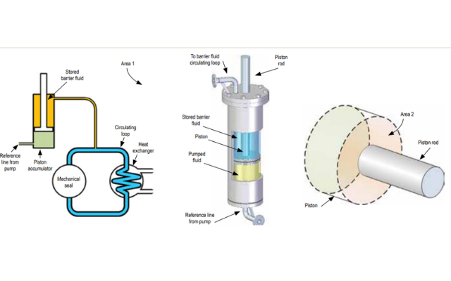
There are many methods to pressurize the barrier fluid for a dual pressurized mechanical seal. Each method, or piping plan, uses a different mechanism to apply the pressure to the barrier fluid and, as a result, each has its own set of advantages. One of these methods is American Petroleum Institute (API) Plan 53C. Although not as widely installed as a traditional API Plan 53A system, it does differentiate itself from other methods. API Plan 53C has the ability to change the barrier pressure as the pressure inside the pump changes. This pressure tracking ability makes this system ideally suited to highpressure pumps, or for pumps that tend to experience a wide range of operating pressures. Image 1 (left). Simplified Plan 53C schematic. Image 2 (center). Typical piston accumulator. Image 3 (right). Piston face areas (Images courtesy of FSA) A Plan 53C barrier system consists of two main elements: Barrier fluid circulating loop: A pumping device within the mechanical seal circulates barrier fluid to a heat exchanger, where heat absorbed into the barrier fluid is dissipated and then the fluid is returned to the mechanical seal. • Piston accumulator: Stores barrier fluid and amplifies pressure from the pump to pressurize the barrier fluid circulating loop.
Loading registration