Theory Bites: System Curves: Pumps In Parallel
Theory bites are a collection of basic hydraulic theory and will touch upon pump design and other areas of pump industry knowledge.
Theory bites are a collection of basic hydraulic theory and will touch upon pump design and other areas of pump industry knowledge.
Flow Rate Added
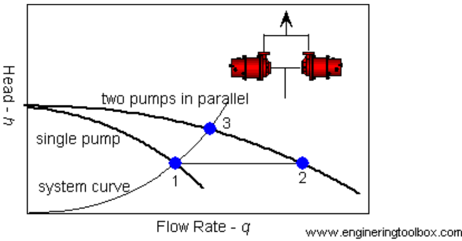
When two or more pumps are arranged in parallel their resulting performance curve is obtained by adding the pump’s flow rates at the same head as indicated in the figure below.
Centrifugal pumps in parallel are used to overcome larger volume flows than one pump can handle alone.
• for two identical pumps in parallel and the head kept constant – the flowrate doubles compared to a single pump as indicated with point 2 Note! In practice, the combined head and volume flow moves along the system curve as indicated from 1 to 3.
• point 3 is where the system operates with both pumps running
• point 1 is where the system operates with one pump running
In practice, if one of the pumps in parallel or series stops, the operation point moves along the system resistance curve from point 3 to point 1 – the head and flow rate is decreased.
Note that for two pumps with equal performance curves running in parallel
• the head for each pump equals the head at point 3
• the flow for each pump equals half the flow at point 3
Note:
• zero flow or “shut valve” heads must match for the pumps
• unstable pump curves must be avoided
• steeper pump curves are preferred
Read more Theory Bites!
Source: Engineering Toolbox